The rockets
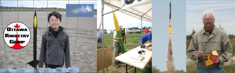
Model Rockets are usually simple. They have a set of fins, a body tube, a nosecone, a parachute for recovery and a rocket motor to make it go. The motor burns and propels the rocket, the propellant in the motor burns out, the rocket coasts upwards and finally arcs over at the peak of its flight (apogee) where a small ejection charge pops the parachute out so the rocket can float back to earth safely. Model rockets are constructed of cardboard, plastic, and balsa wood and are fueled by commercially manufactured single-use rocket motors. Some of the electronics used in High Power Rockets are also employed in model rockets.
Some High Power Rockets operate as simply as Model Rockets, but others have added components to insure more accurate deployment of the parachute or parachutes. A Piston can be used above the deployment charges to aid deployment and protect the parachute from the heat of the black powder charge. Most Model Rockets, and some High Power Rockets, use timed “delay elements” in the motor to ignite the ejection charge, deploying the parachute at apogee. Choosing the right delay is crucial and often difficult. Therefore, many High Power Rockets use an electronic altimeter to deploy the parachute instead of a motor ignited ejection charge. When the altimeter senses that the rocket is no longer climbing, it triggers an igniter which lights a small black powder charge blowing the nosecone off the rocket and deploying the parachute. Altimeters are also used to determine the altitude, speed and acceleration of a rockets flight. A second altimeter is often included to provide back up in the event the initial altimeter does not perform properly; this is referred to as “redundant deployment”.
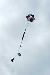
Many High Power Rockets use “dual deployment” where two parachutes are used in the rocket; a smaller drogue chute, or a streamer, deploys at apogee and a larger main chute deploys later at a pre-designated, lower altitude. Several configurations are used for dual deployment rockets. However, most often the rocket is designed so the small parachute deploys from just above the motor section; the mid section, or payload bay, houses the altimeter; and the main parachute is deployed just behind the nosecone. The rocket falls fast on the small chute, bringing it closer to the ground, before a larger chute deploys slowing the rocket’s fall to insure a soft landing. This system increases the chances of a successful recovery by minimizing the distance a high flying rocket drifts “under chute”.
While some High Power Rockets fly on single use motors, most utilize reloadable motor systems or RMSs. RMSs are commonly constructed of machined aluminum, are referred to as “motor hardware” and vary by manufacturer. There are several different designs of motor hardware and while some hardware may by utilized for different “motor reloads”, most are brand specific. Rocket Motors used in High Power rocketry most commonly consist of Ammonium Perchlorate Composite Propellant or APCP. The propellant in motor reloads is sold pre-cast in cardboard or plastic tubes, ready to be loaded into motor hardware. These tubes of propellant are referred to as “grains”; in general, the size of a motor varies according to the diameter and number of grains. Some reloadable motors come as a kit that includes o-rings, nozzles, washers and other components; a clear set of instructions is included with all reloadable motors and should be followed explicitly. If assistance is needed in building a rocket motor at a launch, an experienced rocketeer can always be found. In fact, many clubs ask experienced rocketeers to wear special shirts or orange vests so they are easily identifiable to newer members in need of assistance.
Rocket motors are measured in “total impulse” and are designated by letters of the alphabet. Each letter designates a range of total impulse and each motor size contains twice the total impulse of the previous letter. For example a “B” motor has a potential total impulse twice that of the total impulse of an “A” motor; a “C” motor has twice the potential total impulse of a “B” motor, etc. Rocket motors larger than “G” are considered High Power; use of them requires certification by Tripoli and/or NAR.
Motors are retained in rockets in several ways. Traditionally Model Rockets use masking tape to hold in the motors; High Power Rockets often have more elaborate retention systems as the replacement of lost reloadable motor systems is costly. Some rocketeers use commercially available motor retainers that rely on threaded caps, snap rings or brass inserts while others create their own “custom retention systems”.
The old style of launch rods used as a launch guide to keep the rocket pointed straight up while being launched are giving way to launch rails. Instead of using sections of round tubing to fit the launch rod, rails require only small spool-looking buttons as guides that fit into a slot on the launch rail. It’s far more efficient and much steadier on the launch pad than using a rod. Both rods and rails are used at most launches.
Once the rocket is ready on the launch pad an electrical igniter (two wires with a head made of a easily ignited type-of propellant mixed with magnesium or titanium) is installed all the way up until the head of the igniter stops at the head of the motor.
The igniter wire is then hooked up to a solenoid switch that acts as the igniter’s link to a nearby car battery. The solenoid is wired to a launch control box where each pad can be independently selected and activated by the Launch Control Officer (LCO) at the range head.
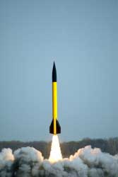
Once energized, ignition in Model Rockets takes only a fraction of a second but High Power Rockets can take a full second or two to “come to pressure” before launching off the pad. As Ammonium Perchlorate Composite Propellant is a difficult material to ignite, some igniters burn out without igniting the rocket motor; rockets that fail to light are often greeted with a chorus of “No Joy” from rocketeers on the flight line.
The Rocket Motors
Rocket motors come in many sizes. They are measured in “total impulse” and are designated by letters of the alphabet. Each letter designates a range of total impulse and each motor size contains twice the total impulse of the previous letter. For example a “B” motor has a potential total impulse twice that of the total impulse of an “A” motor; a “C” motor has twice the potential total impulse of a “B” motor, etc. Rocket motors larger than “G” are considered High Power; use of them requires certification by Tripoli and/or NAR.
Chart of Rocket Motor Impulse by Letter Designation
So their potential power is indicated by a letter. However a motor of any given energy range might be configured to deliver only the middle of energy range rather than the full amount. That’s because you don’t always want the full amount. The motor manufacturer’s charts give you this information. The letter is followed by a number. The number tells you what the average thrust is. An example would be an I-170 or an I-240.
We’re used to speaking in terms of horsepower and such, however, that’s only part of the equation, the amount of time you apply a given amount of horsepower is needed to figure the total energy used. In rocketry we use a different measurement and it’s related to the total energy of the motor, i.e., power and time. Rocket motors are rated in Newton-seconds, however if you divide it by 4.45 and you’ll get pound-seconds. In other words so many pounds of force for one full second.
I don’t want to lose you here so let me give you a little comparison that makes it simple to understand. Think of the term “Newton-seconds” (or pound-seconds) as a way to express the amount of energy in four ounces of gasoline. One ounce of gasoline has 50.7 Newton-seconds of energy so four ounces of gasoline has 202.8 Newton-seconds (or 45.6 pound – seconds) of energy. With it, you can propel a car very fast for a brief time or slow for a long time. Either way you’ll burn up four ounces of gasoline and consume the same amount of energy (202.8 Newton-seconds or 45.6 pound – seconds). The choice is in how to use the energy, fast and brief or slow and long.
Lets say you want to use a “G” motor to launch a rocket you’re choosing between a G-40 motor or a G-80 motor. Both are “G” powered motors and both have 120 Newton-seconds of energy in this case. As I said, the number after the letter means the average thrust, so the two G motor examples have a thrust of either 40 or 80 Newtons (not Newton-seconds). Divide 40 or 80 Newtons of thrust by 4.45 and you’ll get pounds of thrust. So the G-40 produces an average of 9 pounds of thrust and the G-80 produces an average of 18 pounds of thrust. Ahh Ha! – If I have a one pound rocket I can now see the ratio of thrust to the weight of my rocket. The choice is again, fast and brief or slow and long. In general, the safe minimum lift-off weight ratio is 10:1. IE. 10 lbs. Of thrust for every 1 lb. of rocket. Because the total energy contained in both these “G” motors is 120 Newton-seconds (or 26.9 pound-seconds) it means the G-40 will burn for 3 seconds and the G-80 for 1.5 seconds. See, lots of thrust for a brief time or half as much for twice as long. For some detailed motor statistics go to http://www.thrustcurve.org.
Delay Time
The rocket is traveling very fast at the moment the motor quits burning. The timed delay allows the rocket to coast to its maximum altitude and slow down before the parachute is ejected by the ejection charge. The ideal delay time for a rocket and a given motor can be calculated. Better yet, you can use RockSim software by Apogee Components Inc. to predict both the altitude and coast time very accurately. Rocketry Online also has a great information page for computing recovery needs on http://www.info-central.org/index.cgi?recovery.
Model rocket motors marked with a time delay of 0 (e.g., “C6-0”) are booster engines for two stage rockets and are designed to ignite the next stage engine immediately once their own thrust is finished. In a multi-stage rocket, you would usually select a very long delay for your topmost engine.
Reloadable Rocket Motors
Propellant for high power rocket motors is usually a solid fuel mixture of ammonium perchlorate called APCP. There are also Hybrid motors that use a cored paper or plastic element and Nitrous oxide that when in combination are ignited in a combustion chamber, ie, motor, produces thrust. However, I’m going to speak of APCP motors first. APCP is a mixture of ammonium perchlorate and a few other elements. In its raw cast form as a cylinder of solid propellant, it can be ignited and it will burn, but not fast enough to create any kind of thrust. As APCP is pressure sensitive, this propellant burns much faster once you contain it in a combustion chamber (motor case) and you carefully calculate the nozzle exit throat to produce just the right amount of pressure to create a fast but controlled burn, resulting in that all important thrust. As the pressure builds inside the combustion chamber, the hot gases exit the nozzle throat, expanding into the nozzle exit cone and continues to accelerate (depending on the design of the nozzle), resulting in an even more efficient use of the stored kinetic energy of the propellant.
There are single use motors and reloadable motors. The single use motors are common up to “G” power. After that, most motors are reloadable. High power motors begin at “H” power so most High Power rockets use reloadable motors. What’s a reloadable motor? Reloadable motors have separate hardware and propellant that you assemble yourself. The motor case and the two ends are reusable. You purchase the motor hardware and reload it over and over. Rocketeers messed up when it came to the description of the “motor casing hardware.” They use the term “motor” interchangeably and it confuses people. Just so you know. Anyway, you buy the propellant and the disposable internal parts as a “motor,” but actually it’s a kit.
Nowadays there are lots of motor manufacturers and each sells hardware that works only for their motors. One company has a system in which the propellant and inner section comes pre-assembled and all you do is screw it into the case. However, the average motor kit usually contains:
- The slugs of propellant (called grains).
- A motor liner (to protect the aluminum casing).
- The delay grain and its components (this is a very slow burning cylinder of propellant that acts like a fuse going to the ejection charge … which is installed as part of the motor even if an ejection charge isn’t being used).
- O-rings
- A nozzle (one company has a graphite nozzle that is reuseable – others are not).
- End closures that attach by threading or snap rings.
- And always, a detailed set of instructions that must be followed to the letter . Even experienced rocketeers set these instructions in front of them and use them to carefully double-check their assembly.
Here is how a reloadable solid fuel motor works:
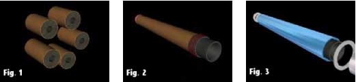
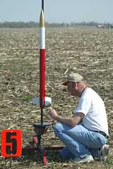
Figure 1: These are APCP propellant slugs (called grains). They are cast in dense cardboard or phenolic liners. The propellant grains are installed in “sections” so the ends will burn as well. This keeps the burn surface area and thrust relatively consistent.
Figure 2: A protective liner has been slid over the stacked propellant grains. This is to protect the aluminum motor case from the heat during the burn time. The liner is fitted with the nozzle and its O-rings that seal the gasses so they can’t escape around the nozzle. A sealing cap is fitted at the head end on this motor.
Figure 3: The propellant, liner, and nozzle are installed and the “end closures” are ready to be installed.
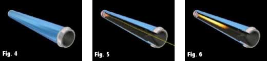
Figure 4: The completed motor ready to install into the rocket.
Figure 5: Once the motor is installed into the rocket and the rocket is on the pad, the electric igniter fires to begin the launch. The igniter is covered with a more easily ignited sort of propellant mixed with magnesium or titanium to start the motor burning good. It only takes a fraction of a second in smaller motors but may take a second or two on big motors.
Figure 6: The propellant grains ignite and the motor begins to pressurize. Thrust builds very quickly at this point.
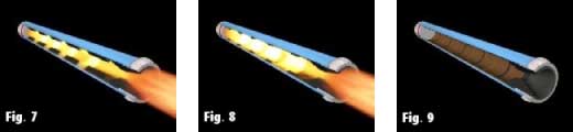
Figure 7: Here’s a perfect illustration of the burning process in a motor. See the burning grains of propellant? The grains burn both at the core area and the ends. This way the burning surface area doesn’t keep increasing.
Figure 8: The motor is still burning fiercely but you can see the APCP fuel grains are getting small.
Figure 9: The propellant grains are nearly gone and the motor exhausted. This does not mean that the rocket has stopped. In fact, the rocket is traveling at it highest velocity at motor burn-out and continues to climb (coast) for a considerable length of time.
It’s always easy to find a rocketeer to help you assemble your first couple of motors.
Physical size
Motors also come in standard diameters. I’ll list them and the powers usually found in that size but know that they overlap somewhat. This allows for versatility in rocket design. Each diameter also comes in different lengths to make the different powers possible.
- 29mm Used for H thru I power motors. (G motors are also normally 29mm)
- 38mm This, the most common high power motor size, is used for H thru J power motors.
- 54mm Motors for 54’s usually begin at J and go to L power.
- 75mm (or 76mm) Also called 3-inch motors. They are usually K thru M in power.
- 98mm Also called 4-inch. These big honkers are for L thru N power motors.
- 152mm This is six inches. These are the mega-motor cases for O power.
Motor manufacture web sites:
- Aerotech (Check the Aerotech website for illustrations of the motor components)
- Animal Motor Works
- Cesaroni